
Video
We continue this series by looking at how to configure the vertex buffer with vertices.
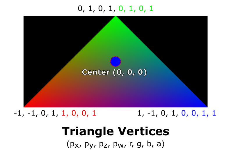
The vertices will be packed into the GPU buffer in such a way to constitute the three points of the triangle like this:

Can’t Wait For The Series To End?
If you would like to move ahead without waiting for the next video in the series, I recommend scrolling down to the code below, or checking out my Rendering a Triangle in WebGPU article.
The WebGPU Triangle Video Series Code
During this series, we will study this code which you can find in this article where we begin the series.
Before being able to render this code, you need to download a browser that is able to run WebGPU code
The vertices
The vertices of a WebGPU scene are points that we want to render. Imagine a triangle like this:
This triangle has three points (obviously).
In graphic terms, these three points are vertices. It is our job to define the attributes of each vertex.
We can define any attribute as long as they are represented as a number or several numbers (floating point, integer, etc). We’ll see what this means in a bit.
The vertices of our triangle
In the code, I define these three vertices:
const vertices = new Float32Array([
    -1.0, -1.0, 0, 1, 1, 0, 0, 1,
    -0.0, 1.0, 0, 1, 0, 1, 0, 1,
    1.0, -1.0, 0, 1, 0, 0, 1, 1
]);
At first glance it’s probably not obvious, but I defined two attributes for each vertex.
What?!
The two attributes I defined are position and color. Every vertex has these two attributes.
Additionally, these attributes are nicely packed in a single buffer as you can see.
To better see exactly what I mean, let’s look at the image below:
For reference, I here’s our vertices buffer once again:
const vertices = new Float32Array([
    -1.0, -1.0, 0, 1, 1, 0, 0, 1,
    -0.0, 1.0, 0, 1, 0, 1, 0, 1,
    1.0, -1.0, 0, 1, 0, 0, 1, 1
]);
On the first line of the vertices buffer - we see -1.0, -1.0, 0, 1, 1, 0, 0, 1.
The first four numbers represent the position of a given vertex:
If the fourth coordinate, , confuses you, that’s okay! It is not important for the moment, but I recommend that you to take a look at this article on homogeneous coordinates if you’re curious.
If the center of our triangle is at the point (0, 0, 0, 1), a position of (-1.0, -1.0, 0, 1.0) means that the vertex is to the left and down.
Can you determine what point this is on the triangle?
The bottom left red point !
We also see that the next four floating point numbers are defined as 1, 0, 0, 1.
They represent the vertex color in RGBA (Red Green Blue Alpha) mode.
So, using the numbers above, we should see red. Why?
Let’s break down each number! :
- R: 1, which means 100% of the red channel should be used.
- G: 0, meaning 0%
- B: 0
- A: 1 - the image should be 100% opaque.
We should therefore see this vertex as red!
OK, but how is it possible for our application to differentiate between these two attributes?
We need to create a descriptor. Let’s go !
We’ll see how these attributes are used in a vertex shader in a later article.
Vertex Descriptor
The vertexBuffersDescriptors are instructions instructing the GPU how to decode the buffer.
const vertexBuffersDescriptors = [{
    attributes: [
        {
            shaderLocation: 0,
            offset: 0,
            format: "float32x4"
        }, // POSITION
        {
            shaderLocation: 1,
            offset: 16,
            format: "float32x4"
        } // COLOR
    ],
    arrayStride: 32,
    stepMode: "vertex"
}];
In our case, we use 32 bytes to describe all the attributes of a given vertex. In our shaders, the GPU will be able to find the position vector at offset 0, and the color vector at offset 16 - as we have already seen.
We also define arrayStride to and the stepMode to vertex which means that for each 32 bytes, the GPU should also parse the attributes for the next 32 bytes as defined in the attributes field.
The field in each attribute definition, shaderLocation will be needed when we define our shaders and render pipeline. For now, the values I’ve used work fine.
Create the GPU Buffer
After defining our vertices, we create the vertexBuffer which is the buffer that will live in the GPU by calling device.createBuffer(). This function takes several arguments:
- size - the buffer size in
bytes. - usage - we describe how the buffer will be used during its lifetime. We define its value as bitwise flags.
- mappedAtCreation - A mapped buffer means that the CPU can access it, and the GPU cannot. Conversely, if the buffer is unmapped, the GPU will be able to access it and the CPU cannot.
Let’s take a look at the code :
const vertexBuffer = device.createBuffer({
    size: vertices.byteLength,
    usage: GPUBufferUsage.VERTEX | GPUBufferUsage.COPY_DST,
    mappedAtCreation: true
});
new Float32Array(vertexBuffer.getMappedRange()).set(vertices);
vertexBuffer.unmap();
After the vertexBuffer is created, it can be accessed by calling getMappedRange().
Next, we invoke .set() to copy our vertices into the GPU buffer. Finally, we remove write access from the CPU and grant read access to the GPU by calling vertexBuffer.unmap().
The Code for Part 4
You can find the code for this part in this GitHub Gist.
Next Time
We’ll move forward with this project and aim to cover some more topics as we render a WebGPU Triangle together.